You can get more background on the technology here:
How DLP Works
Unfortunately, for whatever reason some of the chips had a higher than normal failure rate. One symptom of a failure is the appearance of white or black dots in the picture. You can do a simple web search and see an abundance reports regarding this issue.
Fortunately, this issue is relatively simple to correct. Just replace the DMD chip. If you can feel comfortable working on a PC you can most definitely do it.
I got my DMD chip from ShopJimmy.com.
First watch this good generic video... it will walk you through the concepts of what you're going to do.
Samsung 4719-001997 DLP Chip Replacement Guide for DLP TV
Now for a few tips specific to the HL61A750.
Remove the rear cover. There are 10 screws to remove. Six are shown. There are an addition two screws on each side.
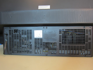 |
| Samsung HL61A750 Rear Cover |
After you remove the rear cover, this is what you'll see:
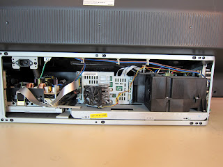 |
| Rear Cover Removed |
Although the ShopJimmy video says you'll need to remove/slide out the light engine assembly, that is not necessary for this model. I did, and it was a pain keeping dust off all the mirrors. You really don't want to do it.
What you need to do is remove the fan. This can be accomplished by using a short screw driver. Remember, take pictures and make notes. You are going to be removing 20 or so screws and unplugging a few cables, so you want to be sure to remember what goes where.
Here is a photo of the fan removed:
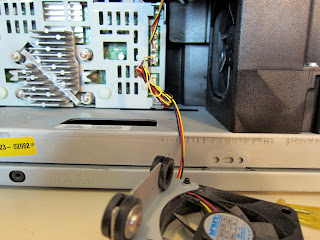 | ||||||||
| Heatsink Fan removed |
You can see the two screw holes for the fan in front of the heatsink. Note the orientation of the power connections for the fans. Note also that these cables need to be removed before the DMD board cover can be removed.
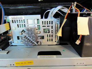 |
| Fan Connectors Unplugged |
Now, use your needle-nose pliers and carefully remove the metal strap holding the heatsink in place. Yes, that is all that is holding the heatsink.
Remove from the top left.
Now you can also remove the four screws holding the DMD Board cover in place. Remove the board cover by pulling straight back.
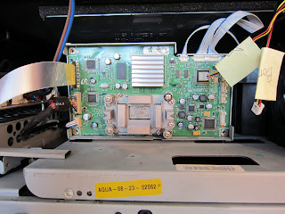 |
| Heatsink/Board Cover Removed |
Now carefully disconnect the remaining five cables. The ribbon cable on the top left you pinch from the top and bottom and pull straight back. The remaining cables have a latch you need to push in on the side from the bottom the carefully pull either up or straight back.
Now remove the DMD circuit board.
Remove the three screws firmly holding the board in position. There are two on the left, and one on the right. Then remove the four positioning screws (the ones with the springs). Now you can remove the circuit board. Carefully pull straight back.
You'll now see the DMD chip on the back of the board. Remove the DMD chip cover. Do this by removing the four remaining screws. You could have alternatively done this before removing the DMD board from the housing.
Carefully pull the chip straight back from the board. You can also carefully push from the otherside. I did both. Go slowly, you don't want to bend the pins.
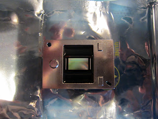 |
| DMD Chip Front |
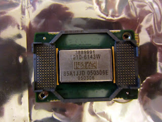 |
| DMD Chip Back |
Now reverse the procedure to put everything back in place. Note the chip has a notch, so it can only be installed one way. Be extremely careful not to bend the pins. On my set there was nothing locking the chip to the board other than the screws and the chip cover.
Now, what I would recommend is you test the positioning of the display before completely putting everything back together. Don't put the DMD Board Cover back on, nor the heatsink.
 | |||
| Heatsink/Board Cover Removed |
Now you're going to test the display. Make sure all the cables are reconnected, including the three fan cables. This also means the heatsink fan also needs to be connected to power, but not connected to the set chassis. If it isn't connected you'll get a nasty message when you power-on the TV. Remember the three screws which were firmly holding the board in position? Put them in loosely. Have the four screws with springs connected relatively loosely, but not too loose, they are holding the board in place just enough so you can move it. The four screws which are holding the DMD Chip Cover to the back of the board of course are tightened.
What you will notice is the board has a little bit of play in it. We're talking millimetres of play - but on the display, this translates into inches. When I first powered my set on, I noticed a five inch band of black on the top of the screen. Have someone turn on the TV, use the remote and go to the Menu. This will give you a reference point. Slowly, carefully tap on the board to move it in the same direction of the issue. If the display is too low, tap it down, the picture will move up. If the screen is slanting upward to the right, tap the board so it moves upward to the right. Again, we're talking very slight corrections here. Once you are satisfied with the position of the display, turn off and unplug the TV. Tighten the three position screws to lock the board in position. Be careful not to move the board.
Now continue reconnecting everything.
The procedure sounds a little intimidating, but actually isn't that bad. Just take your time.